Product Specification Definitions
Product Specifications
1) Input Range
The input range of an accelerometer or inclinometer is the region between the input limits from negative (–) to positive (+) values over which the transducer is expected to yield the specified output. For example, a ±2g accelerometer has a full input range of 4g (-2g to +2g), centered on 0g. Both Force-Balance & MEMS type sensors tend to have wider output ranges up to ±90° & ±20g, whereas Electrolytic sensors can range up to ±80°.
2) Full-Range Output (FRO)
Full-Range Output is the total change in output the sensor has for its full negative (-) to positive (+) range of input acceleration or tilt. For example, an inclinometer with a ±90° (-90° to +90°) input has a full range output of ±5 Volts (-5V to +5V) or 10 Volts. For a sensor with 4-20mA output, the FRO would be 16mA, which a -90° tilt would have an output signal of 4mA and output of 20mA for a +90° tilt.
3) Full-Scale Output (FSO)
Full-Scale Output (FSO) is the change in output the sensor has for an input going from zero to positive or negative full scale. For example, a standard ±90° inclinometer has a full-scale output of 5 Volts for an input change of +90° or -90°.
This term is sometimes mistakenly used to specify Full Range Output. Note the difference in values here using a sensor with ±90° range & ±5V output as an example:
– Full-Range Output (FRO) over the full input range is 10V (-5V to +5V)
– Full-Scale Output (FSO) is 5V (absolute value is the same: from -5V to 0; and 0 to 5V)
Accuracy is dependent upon the application, and it should be tailored to the error sources that apply. Accuracy is only meaningful in qualifying a sensor if it fairly applies to the application. How one defines total error or accuracy is not universal.
-
- Depending upon the unit installation in the application and environmental conditions, other factors affecting the precision of the sensor’s output reading could come into play in addition to non-linearity such as:
-
- Environmental Temperature
-
- Level of mounting surface
-
- Vibrational environment
-
- Presence of electrical interference or ground loops
-
- The sensors sensitivity range vs the actual measured force
-
- Depending upon the unit installation in the application and environmental conditions, other factors affecting the precision of the sensor’s output reading could come into play in addition to non-linearity such as:
-
- Determining what precision can be achieved depends upon those factors that can be compensated for in the application and those that are not repeatable or cannot.
-
- For instance, in the application installation, several factors must be taken into consideration:
-
- What is the expected temperature range?
-
- Is there a means to correct the sensor sensitivity error?
-
- Is there a means to correct the sensor 0° output error?
-
- Is there a means to remove the sensor axis misalignment error?
-
- What sort of vibrational profile will the sensor be subject to?
-
- Will low-pass filtering be used that could reduce signal noise?
-
- In lieu of the above, will digital signal processing be used for reducing sensor errors?
-
- For instance, in the application installation, several factors must be taken into consideration:
-
- Correcting the big error sources has the biggest impact on sensor accuracy (primarily those are the ones mentioned above). Other error sources, like non-linearity, are small by comparison and don’t contribute as much to accuracy. Sensor non-linearity typically is better than the equipment on which it is measured, meaning that equipment is the limiting factor for what can be reported (See the non-linearity section below to learn more).
-
- To Summarize, Accuracy specifications on inertial sensors are relatively easy to understand but are often a difficult specification to achieve in a real-world application due to all the variables and specifics of an application, and the detailed conditions in which they exist.
For static applications involving our electrolytic product line (especially the 700 & 600 series) and customers have high-end accuracy concerns, we do offer full characterization across temperature. This process will begin with the customer’s determination of the temperature range of interest, and how many temperatures they want us to test at. We will then thermally pre-stress the sensors, and characterize them across several angular positions at each temperature. This data is then published along with Ks and Kz calculations so that you can perform bilinear interpolations, Ks & Kz compensation, or any compensation scheme that customer deems appropriate to remove the temperature variation effect to maximize accuracy. Some customers may choose 3 point characterization, likely {-25C, 0C, +25C} for their application. Some others have gone for 5-point and 7-point characterizations. There’s a testing fee per axis per temperature as this is currently a labor-intensive process. The scientific research community has contracted us in the past for 7 temperatures.
Axis Misalignment is typically listed on Jewell datasheets as Output axis misalignment, however there are three distinct types of axis misalignment which can be considered:
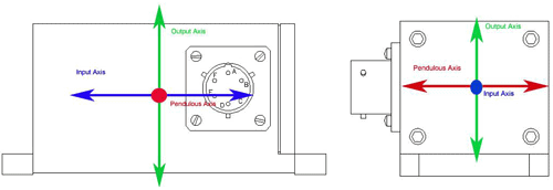
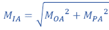
1) Input Axis Misalignment (MIA)
Input Axis Misalignment is the angle (degrees) which the sensor has between its input axis and associated input reference axis when at its minimal output condition.
The angle the sensor has between its input axis and associated input reference axis when at its minimal output condition. (IEEE standards use both direction cosines and right-handed Euler angles, depending on the principal field of application. Other conventions, differing both in signs and designation of axes, are sometimes used. When components are reported, the convention should always be identified.) The input axis misalignment is the geometric sum of the output axis and the pendulous axis misalignments relative to the sensor’s base and a reference side respectively:
2) Output Axis Misalignment (MOA)
Output Axis Misalignment is the angular deviation or alignment error the sensor has between its output axis (true sensing axis) and the output reference axis as defined by the case. The basic Jewell equation is:
Output Axis Misalignment (MOA) = (Output0° – Output180°) / 2
Dividing the result with Scale Factor gives the misalignment in g. The g-result is converted to misalignment in degrees using the Arc-Sine function.
Output axis misalignment is reported as a maximum value in degrees, for example the LCA-165-1 output axis misalignment is 1.0°.
3) Pendulous Axis Misalignment (MPA)
Is the angular deviation or alignment error the sensor has between the pendulous axis (true sensing axis) and the pendulous reference axis as defined by the mounting case. The basic Jewell equation is:
Pendulous Axis Misalignment (MPA) = (Output-90° – Output+90°) / 2
The misalignment may at times be measured at angles other than ±90 degrees.
The scale factor is the ratio of change in output per unit of input. For example, a ±2g full range accelerometer with ±5 Volts output will have a scale factor of 2.5 Volts/g whereas a ±1° Inclinometer with ±5 Volts with will have a scale factor of 286.5 Volts/g. Jewell typically specifies scale factor as the sensor units of output per g, such as Volts/g for example.
For an inclinometer with ±3° range having a ±5V output, the Scale Factor can be found as:
SF = 5/sin(3°) = 5/0.052 = 95.53 V/g
Going the other way, to calculate the angle from an output voltage for the same example mentioned above:
θ = asin (Vout/SF) = asin (5/95.53) = 3.00°
The ratio of the sensor output to input range. It is usually in units of Volts per g (V/g) or other similar units of measure and is the basic sensor transfer function used in calculations such as a sensor output to its corresponding input acceleration or tilt.
1) Temperature Sensitivity
The temperature sensitivity of a Jewell sensor is normally determined over two segments of the operating temperature range, which are room-to-cold and room-to-hot.
2) Scale Factor Temperature Sensitivity (SFTS)
SFTS is the sensitivity defined by the ratio of change in scale factor to a corresponding change in
Temperature, it is calculated using the following equation:
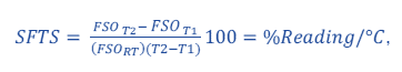
where FSO is the full scale output measured at T1 and T2 , the respective temperature at which FSO measurements were made. FSORT is the full scale output measured at room temperature. The same equation can be used to calculate SFTS in ppm/°C by multiplying the quotient by 10^6 (1,000,000) instead of 100.
3) Bias Temperature sensitivity (BTS)
Bias Temperature Sensitivity is the ratio of a change in output bias for a corresponding change in temperature. Bias Temperature Sensitivity is calculated using the following equation:

where Bias is the bias calculated as given in the glossary definition of Bias and T1 and T2 are the temperatures at which measurements were made, where T2 is the higher temperature.
BTS can also be calculated with the result in g units as follows:

where SF refers to the Scale Factor.
4) Zero-Degree (0°) Output Temperature Sensitivity (ZTS)
The sensitivity defined by the ratio of change in output with the sensor at zero degrees to a corresponding change in temperature. It can be calculated using the following equation:

Bandwidth refers to the dynamic response of the sensor. It is the range of frequency over which the sensor will respond to an input with an output that does not fall more than 3 dB below the flat (full) amplitude. Force balance sensors typically have a bandwidth from 1-200Hz, whereas MEMS typically ranges from 1-1000Hz. Electrolytic sensors tend to have a low bandwidth of < 10Hz – Electrolytics are intended for measurements of stationary objects. Bandwidth can be intentionally influenced by dampening employed via electrical filters or shock absorbing oil added to the torquer assemblies in the case of some force balance assemblies. These technologies can be used to remove unwanted elements of the vibrational profile in the operating environment, by manipulation of the sensors dampening ratio (see the dampening ratio below for more).
The bias is the accelerometer output when no acceleration is applied. The output of an inertial sensor held stationary on a flat surface is from bias combined with misalignment and noise. The magnitude of bias can be either or the combination of residual mechanical torque (force balance only) or electrical offsets in the electrical circuit of the sensor. Taut band based force-balance accelerometers have improved mechanically caused output bias compared to pivot and Jewell based sensors (click here to learn more). MEMS output bias is typically only caused by electrical offsets. Generally output bias may be treated as a constant and can be offset via the users equipment via subtracting the bias value from the output.
The same applies to our electrolytic tiltmeters. In short, the tiltmeter bias can be defined as the difference between the true angle and the angle reported by the tiltmeter. Think of a perfectly horizontal surface with an Jewell tiltmeter sitting on it. If there were no bias, then the tiltmeter output would read 0 degrees (assuming bipolar output). However, tiltmeters will read something different than the ideal 0 degrees on a perfectly horizontal surface because of mechanical tolerances in the component parts (base plate, screws, standoffs, etc.).
To measure and remove bias, do the following:
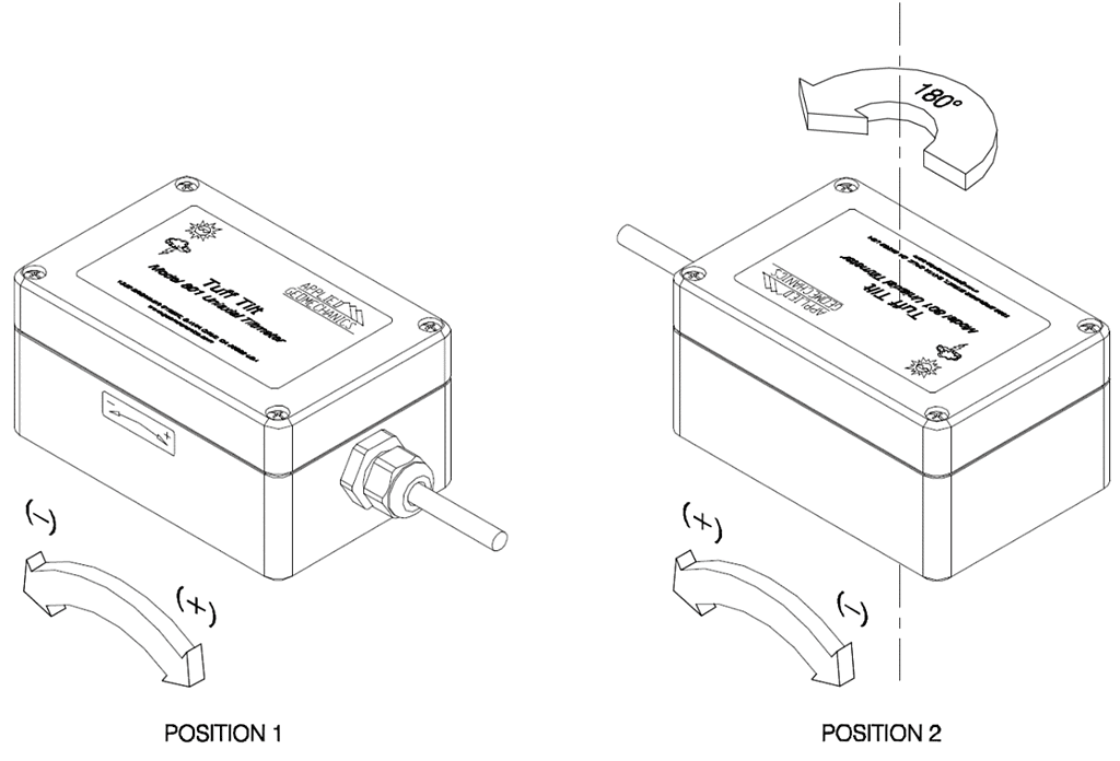
1. Place the tilt sensor on an approximately horizontal surface (tabletop, granite flat, etc.). Read the indicated angle, Output0°. For voltage output tiltmeters, Output0° = V x S, where V is the voltage and S is the scale factor reported in the user’s manual.
2. Rotate the tiltmeter 180 degrees on the surface so that it is facing the opposite direction. Read the indicated angle Output180°
3. Calculate Bias using the following equation:
Bias = (Output0° + Output180°) / 2
Record Bias and subtract it from all subsequent measurements to get the true angle. 4. For biaxial tiltmeters biases for both tilt axes, Bias (X-axis) and Bias (Y-axis) should be measured.
The proportionality constant (g/g) that relates a variation of accelerometer output to cross-acceleration. This sensitivity can vary, depending on the direction of cross acceleration.
Non-linearity is the largest deviation in the accelerometer output over its specified input range when the output is compared to a least-squares-best-fit line. Improvements to nonlinearity are generally not required or practical. For inclinometers and accelerometers of 5g full scale or less, nonlinearity errors are often small enough to be ignored. Nonlinearity is typically expressed as the max of %FRO (Full Range output). A more in-depth review of these calculations can be found in our Non-Linearity Calculations Inertial Tech Note.
Resolution is the smallest input change anywhere in the operating range that will result in at least the 50% of the expected output change, nominal scale factor. Typically, Jewell measures it at the full-scale input or at one-half the full-scale input.
-
- Jewell MEMS technology can reach 0.0001° resolution
-
- Jewell Force-balance technology offer resolution as fine as 0.000057° (1μrad)
-
- Jewell Electrolytic technology is unmatched at 0.000000143° (2.5 nanoradians)
Repeatability defines an area of output uncertainty within which the sensor may yield different outputs for identical inputs. The uncertainty is primarily a function of moving system suspension friction and position errors. Flexure suspension units have relatively small repeatability errors. Observed repeatability is application dependent.
In other words, repeatability refers to the closeness of agreement among a number of consecutive measurements of the output for the same value of the input under the same operating conditions, approaching from the same direction. For static applications, the electrolytic sensor (especially the 500, 600 & 700 series) offer the highest repeatability compared to other technologies on the market.
Note that Turn-on repeatability refers to the uncertainty of an output from a sensor when it may yield different outputs under the same input conditions after the sensor has been powered off and then back on. This is also referred to as Bias Uncertainty when the sensor is at zero g input and power cycled off and on.
Damping is defined as the energy dissipating characteristic which, together with the natural frequency, determines the limit of frequency response and the response time characteristics of an accelerometer/inclinometer. In response to a step change of input, an under-damped (periodic) system oscillates about its final steady value before coming to rest at that steady value; an over-damped (aperiodic) system comes to rest without overshoot, and a critically damped system is at the point of change between the under- and over-damped conditions. Viscous damping uses the viscosity of fluids (liquids or gases) to produce damping. Magnetic damping uses current induced in electrical conductors by changes in magnetic flux to produce damping.
The damping ratio (ζ) characterizes the shape of the sensor dynamic response. It is defined as the ratio of actual damping compared to critical damping for a second-order system. Typically, for Jewell sensors the ratio equals 0.707 of the Full-Scale Output (FSO) but it can range from 0.5 to 1 depending on the specific product or customization.
Natural Frequency is defined as sensors Output frequency where the phase of the output lags the input by 90°. For Jewell Force-Balance sensors, the Natural Frequency typically is identical to the bandwidth of the device if the dampening ratio equals 0.707 of the Full-Scale Output (FSO).
A transverse axis is an axis perpendicular to the input or sensitive axis of the sensor. The output axis and the pendulous axis are both transverse axes.
Noise is the dynamic output from the accelerometer when no acceleration input is present. Measuring true servo accelerometer noise output is a challenging task since there is almost always some environmental vibration present, and the sensor noise is extremely low. Environmental accelerometers pass band noise of 0.001g in an office, and 0.005g to 0.010g in a factory, is not surprising. The published noise specification reflects what a typical user might find when looking at accelerometer AC output in a laboratory or office, not the actual transducer noise. Accelerometer broadband noise tests results of less than 20 µvolts rms are typical. The true output noise level is not likely to be a significant error to most users.
When evaluating the level of output noise, it is important to minimize input variations by measuring noise at a location that is free of seismic disturbances. Accelerometers and inclinometers respond to even the slightest seismic disturbances within the pass-band and that can easily add to the noise measured at the output, increasing the overall broadband noise and resulting in an inaccurate output noise measurement. Lower input range units are particularly plagued with this measurement problem due to their increased sensitivity to seismic noise.
Output impedance is the impedance presented by the sensor output to a load. The standard output configuration for most Jewell inertial products is an operational amplifier with 100 Ω in series. There are other configurations including direct output across a sense resistor which can exceed 5,000 Ω. Individual data sheets must be referenced where sensor output impedance is critical to an application.
The operating temperature range defines the temperature extremes over which the accelerometer or inclinometer will work without temperature induced failure or a permanent change in some output characteristic. Within this range of temperature, all standard spec performance over that temperature range apply.
The range in temperature as defined by the extremes, within which the sensor will operate without damage or degradation of performance that is permanent. Although the sensor will survive exposure to this temperature range, specified performance is not guaranteed when outside the operating temperature range.
The range in temperature as defined by the extremes, within which the sensor can be exposed while being stored or in an unpowered state that will not cause damage or change in performance. In the case of the electrolytic & fluid-damped force-balance sensors, operating them outside the specified operating temperature range may also cause permanent change in fluid characteristics and negatively affect the performance of such devices which is not covered by warranty.
Shock and vibration specifications indicate the highest level that the accelerometer or inclinometer can be exposed to without causing a permanent change to the unit.
• A mechanical shock is a sudden acceleration of short duration typically caused by an impact or explosion. Shock is measured in the same units as acceleration. Random vibration limits are specified for 3-hour exposure to white noise in the bandwidth 20 Hz to 2000 Hz. For most standard sensors, the highest continuous acceleration level that can be applied without damage is 30G. For example, the Shock specification for the LSO inclinometer series is 1500g, 0.5 msec, ½ sine, and its vibration specification is 20grms.
• Vibration is a mechanical back-and-forth motion consisting of a single frequency or a range of frequencies. A sensor will respond to vibration with what is considered a useable output over its specified bandwidth. As an environmental characteristic, vibration is typically specified as the largest level, sine or random, that the sensor can be exposed to without physical damage or a permanent change in performance.
Force-Balance sensors have a high shock and vibration tolerance, (particularly fluid dampened units) whereas electrolytic sensors are not-well suited to environments with high levels of vibration and shock, as vibration will require some settling time before measurements can begin/resume. Electrolytics are intended to measure static changes on stationary objects.
Sealing specifies the design technique selected to prevent moisture, dust, or other external contaminant from entering the sensor housing. Various sealing approaches are implemented for Jewell sensors. An epoxy seal is effective for normal transducer use as water, dust or other typical contaminants will not enter the housing. Hermetic seals having leak rates less than 10-7 cc/sec/atmosphere are also available. Jewell sensors that incorporate Force Balance, MEMS or Electrolytic sensor technologies have various IP (Ingress Protection) ratings, which are not related to the sensor technology, but to their respective enclosures & the seals they possess. Jewell instruments products range from IP65 to IP68, with the higher ratings typically available via customization.