FAQ (DGH)
A Quick Start document is available from this website for download. The document is also located on the distribution CD-ROM that you received with your order. Visit the Downloads page to obtain it.
Yes, the MK-1 DIN-Rail mounting kit can be used to mount any D-Series module to a DIN-Rail, as illustrated in the picture to the right. The MK-1 comes with two DIN-Rail mounting clips that will accept the captive screws that are shipped with every D-Series module. Simply turn the captive screws into the MK-1 mounting clips and then snap the module on to a DIN-Rail.
A Quick Start document is available from this website for download that contains step by step instructions on how to install the Windows compatible Utility Software. The document is also located on the distribution CD-ROM that you received with your order. Visit the Downloads page to obtain it
The entire DGH product line is designed to withstand the following environmental specifications.
- Operating temperature range: -25 to +70 degress C
- Storage temperature range: -40 to 85 degrees C
- Relative Humidity: 0 to 95% non-condensing
D2000 series modules are a firmware enhanced version of the D1000 series modules.
The D1000 series modules return data values in millivolts, milliamps, hertz, or temperature. These data values often require calculations to achieve the desired data values. The D2000 series modules provide additional firmware commands to internally rescale these data values into desired engineering units that match the application.
Additional commands provide the functionality to rescale both linear and non-linear sensors. Factory programmed linear data values can be easily reprogrammed using the DGH utility software. Our Utility Software can read the present scaling, allow for user changes, and then write the new values back to the module.
Non-linear sensors can be linearized using a piece-wise linear approximation technique and the enhanced command set. The enhanced command set provide up to 23 user-programmable breakpoints for creating a breakpoint table to linearize the output data from a sensor. A breakpoint table can be easily programmed into the module using the DGH Utility Software, or manually programmed by transmitting commands through the serial port.
See the Programming Supplement for more details and examples.
The Modbus RTU protocol is an open serial protocol that is widely used in today’s industrial monitoring and control equipment. This protocol uses a serial RS-232 or RS-485 interface for communications and is supported by almost every commercial SCADA, HMI, OPC Server and data acquisition software program in the marketplace today.
Using a Master/Slave technique, the Modbus RTU is able to communicate between devices. A Modbus Master is typically a host supervisory computer running software that will communicate with Modbus Slave devices. The Modbus Slave devices typically perform measurements and control on/off devices in a system. To perform these tasks, the Master sends messages to a Modbus Slave requesting a specific task to be performed.
The Master messages contain several important pieces of information. Each message includes a Slave address of the device to receive the message, a function number (or command) that will be performed and any data that is required. The Modbus Slave response message contains the responding Slave address, the function number and the data requested by the master.
Many DGH products support the Modbus RTU serial protocol. Including single and multi-channel analog input modules, analog output modules, and digital input/output products.
Read more detailed information about the protocol and the supported Modbus functions.
All DGH Modbus analog input products scale their raw analog input data values using 16-bit unsigned integer values that represent a linear percentage of the full scale input range. These raw data values range from 0 counts (-FS) to 65535 counts (+FS).
The full scale analog input range is determined by either the product model number or the user selected analog input range. These data values represent the analog input +/- Full Scale data values. For example, DC voltage, DC current, temperature, etc..
Determine and enter the proper analog input full scale values with the equation on the right. Then calculate the correct analog input value.
In our example, we will be using the J-Type Thermocouple temperature input range of -200C to +760C. These values are shown in the middle column to the right.
Modbus Scaling Constants
| Raw Data | -FS = 0 Counts |
| Full Scale Values | +FS = 65,535 Counts |
| Analog Data | -FS = -200 DegC |
| J-Type TC Full Scale Values | +FS = +760 DegC |
| Raw Data | 36,769 Counts |
| Example Value |
Modbus Scaling Calculation
| Raw %FS = Raw Data / (+FS – -FS) Raw %FS = 36,769 / (65535 – 0) Raw %FS = 0.561 |
| Data Value = (Raw %FS * (+FS – -FS)) + -FS Data Value = (0.561 * (760 – -200)) + -200 Data Value = +338.56 DegC |
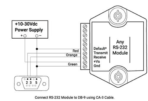
- Using a voltmeter, measure the power supply voltage at the +Vs and GND terminals to verify the power supply voltage is between +10 and +30Vdc.
- Verify using an ohmmeter that there are no breaks in the communications data lines.
- Connect the module to the host computer and power-up each device (module and computer) then using a voltmeter measure the voltage between RECEIVE and GND. This voltage should be between -5 and -10Vdc. Repeat the measurement between TRANSMIT and GND terminals and confirm the voltage value to be between -5 and -10Vdc. If either of the two readings is approximately 0.0Vdc then the communications data lines are wired backwards. Proper communications levels on both TRANSMIT and RECEIVE terminals should idle between -5 and -10Vdc.
- If you are using a serial communications converter (A1000) ensure that the communications Baud Rate switch is set to the proper Baud Rate value.
- Confirm software communications settings in Host computer match those values being used by the connected module(s).
- Those using a Baud Rate value in the application that is greater than 300 Baud and the module will only communicate 300 Baud then make sure that the DEFAULT* terminal is not connected to Ground (GND).
- If the module(s) are being used in a RS-232 daisy-chain communications configuration then ensure that the “Echo Bit” is enabled in the setup(SU) message of each module.
- On the chance that the problem is not corrected after completing the steps above then connect the module by itself to a Host computer as outlined in Chapter 1.0 under “Quick Hook-up”. Start the supplied Utility software and please call the factory for further assistance.
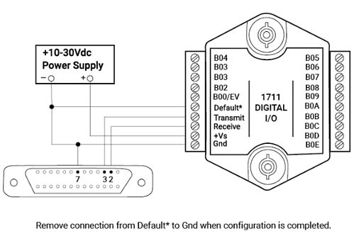
NOTE: The connections in this drawing are the same when connecting other types of modules to a DB-25 serial port.
- Using a voltmeter, measure the power supply voltage at the +Vs and GND terminals to verify the power supply voltage is between +10 and +30Vdc.
- Verify using an ohmmeter that there are no breaks in the communications data lines.
- Connect the module to the host computer and power-up each device (module and computer) then using a voltmeter measure the voltage between RECEIVE and GND. This voltage should be between -5 and -10Vdc. Repeat the measurement between TRANSMIT and GND terminals and confirm the voltage value to be between -5 and -10Vdc. If either of the two readings is approximately 0.0Vdc then the communications data lines are wired backwards. Proper communications levels on both TRANSMIT and RECEIVE terminals should idle at -5 and -10Vdc.
- If you are using a serial communications converter (A1000) ensure that the communications Baud Rate switch is set to the proper Baud Rate value.
- Confirm software communications settings in Host computer match those values being used by the connected module(s).
- If the Baud Rate value being used in the application is greater than 300 Baud and the module will only communicate 300 Baud then make sure that the DEFAULT* terminal is not connected to Ground (GND).
- When using module(s) in a RS-232 daisy-chain communications configuration then ensure that the “Echo Bit” is enabled in the setup(SU) message of each module.
- If the problem is not corrected after completing the steps above then connect the module by itself to a Host computer as outlined in Chapter 1.0 under “Quick Hook-up”. Start the supplied Utility software and please call the factory for further assistance.
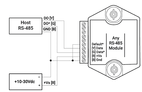
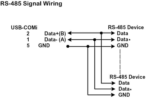
The diagram above is intended to cover as many different host RS-485 serial port designators as possible. The Data line on every DGH module is RS-485 data positive (+) line and the Data* line is data minus (-). Use the following list to further assist with RS-485 communications problems.
1. Using a voltmeter, measure the power supply voltage at the +Vs and GND terminals to verify the power supply voltage is between +10 and +30Vdc.
2. Verify using an ohmmeter that there are no breaks in the communications data lines.
3. If you are using a serial communications converter (A1000) ensure that the communications Baud Rate switch is set to the proper Baud Rate value.
4. When using a communications converter from another vendor, confirm that the converter does or does not require external handshaking signals to control the flow of data on the RS-485 bus. If so, you must configure your host computer software to properly turn the converter on and off when the host computer is transmitting data and not.
5. Confirm software communications settings in Host computer match those values being used by the connected module(s).
5. When the Baud Rate value being used in the application is greater than 300 Baud and the module will only communicate 300 Baud then make sure that the DEFAULT* terminal is not connected to Ground (GND).
6. If the problem is not corrected after completing the steps above then connect the module by itself to a Host computer as outlined in Chapter 1.0 under “Quick Hook-up”. Start the supplied Utility software and please call the factory for further assistance.
The D1711, D1712, H1750 and H1770 digital I/O products can be configured for “continuous mode” operation. In “continuous mode” one device configured as all digital inputs can drive another device configured as all digital outputs without a host computer in between them.
This continuous “master-slave” configuration allows contact closures in one location to be communicated to another location several feet or several miles away without using a host computer. The 1700 series products can use one of three different modes to communicate digital input data and the communications medium can be a multi-conductor cable, RF or lease-line modems.
Digital outputs (“slave”) module configuration commands are listed. There are two commands that are application specific. The Initial Value and Watchdog Timer commands should be reviewed by the user to determine the best value for the application. Using the Inital Value (“IV”) command specifies a “safe-condition” for the digital outputs on power-up. The Watchdog Timer can be used to set the digital outputs to their “initial values” if a communications failure is detected after user-specified amount of time.
The instructions below are detailed list of commands to configure both the digital inputs (“master”) module and the digital outputs (“slave”) module. This configuration command list configures the master module for “continuous timer” mode.
D1700 Digital Input Module
| Command | Response | Comments |
| $1WE | * | |
| $1SU31030102 | * | 4800 Baud |
| $1WE | * | |
| $1AIO0000 | * | All Inputs |
| $1WE | * | |
| $1CT+00001.00 | * | 1 Second |
| $1WE | * | |
| $1CMT | * | Continuous Timer Mode |
| $1WE | * | |
| $1WT+99999.99 | * | Disable Watchdog |
D1700 Digital Output Module
| Command | Response | Comments |
| $1WE | * | |
| $1SU32030102 | * | 4800 Baud |
| $1WE | * | |
| $1AIOFFFF | * | All Outputs |
| $1WE | * | |
| $1CIA31 | * | Continuous Input Address |
| $1WE | * | |
| $1CMI | * | Continuous Input Mode |
Note: The initial value (iv) command and watch-dog (wt) command can also be used at this time for digital output module only!
A sample program is available to communicate with a DGH D1000 series analog input module using an Arduino Mega2560. The sample program illustrates how to setup a Mega2560 serial communications port, transmit a command and receive a response message.
The sample source code is heavily commented and easy to follow. It includes individual functions for sending analog and digital I/O commands such as Read Data (RD), Analog Output (AO), Digital Input (DI), Digital Output (DO) and Read Events (RE). The source code can be easily expanded to include additional protocol commands.
Simply set the baud rate in Setup() and place the three function calls in the main loop() of the program for the fastest command/response processing. See the abbreviated sample code on the right.
The program transmits and receives data on port Serial1 using pins #18 and #19. The serial port pins are TTL level and will required a serial communications interface chip to connect with a DGH module. Select an appropriate interface chip to communicate using the RS-232 or the RS-485 standard.
TESTING NOTE: When using a brand new module from DGH, set the baud rate in the example Setup() to 300, compile the code and start communicating with the module without performing any module setup changes. Higher baud rates will be more beneficial in the final application.
Sample Source Code
#include “dgh.h”
// Define DGH Class
DGHClass DGH;
//
// Program Setup Function
//
void setup() {
// Initialize Serial1 on Mega2560 to 19,200
DGH.begin(19200);
}
//
// Main Loop
//
void loop() {
// **************************************
// STEP 1 : Trigger Any Command
// **************************************
if (DGH.getCommState() == DGH_IOSTATE_NONE)
// Transmit A Command
DGH.RD(ASCII_1);
// **************************************
// STEP 2 : ALWAYS CALL the Non-Blocking Communications Processor
// **************************************
DGH.processCommand();
// **************************************
// STEP 3 : Check for Response Message
// **************************************
if (DGH.msgAvailable()) {
// Process Response
if (strlen(DGH._rxbuf) > 0) {
// Have Valid Response
// Parse the Data Value
}
// Reset the Status Bit – Ready to Send Next Command
DGH.setCommState(DGH_IOSTATE_NONE);
}
}
International orders for DGH products can be placed with our International Distributors. Contact the distributor located in your country and place the order with them. International customers who do not have a DGH distributor in their area can purchase products directly from our factory.
Quoted transportation costs may vary and other import fees may apply for international orders.
We accept Visa, MasterCard, American Express, and Discover through our secure payment portal in our online store.
New equipment may be returned within 30 days of shipment with prior factory approval and upon the assignment of a Returned Material Authorization (RMA), by a DGH Corporation customer service representative. This number must be clearly visible on the outside of the return package(s). RMA numbers are valid for 30 days from date of issue. New items in factory sealed containers which are less than thirty days old after shipment may be returned for credit, less a minimum restocking charge of 20% of the full list price plus all shipping charges, and only with factory approval. Specially ordered, or modified goods, or goods which have been used or have been unpacked from the factory-sealed containers, or goods which have been shipped more than thirty days prior are not returnable.
DGH warrants each product to be free of defects in materials and workmanship under normal conditions of use and service. Therefore, we will replace any component found to be defective upon its return to DGH within one year of purchase. DGH assumes no liability, expressed or implied, beyond its obligation to replace any component involved. Such warranty is in lieu of all other warranties expressed or implied.
| Acquisition Rate | The rate at which samples are acquired. Often referred to in terms of Hz, kHz or MHz. 1 Hz = 1 sample per second. |
| A/D | Analog -to –Digital. |
| ADC | Analog-to-Digital Converter. An electronic device that converts analog input voltage into digital value. |
| Asynchronous | A process or event that occurs without synchronization of time. |
| Bandwidth | The highest frequency signal component that will pass through an amplifier or filter. |
| Baud Rate | A serial communications data transfer rate conveyed in bits per second. |
| Bipolar | An input or output range including both positive and negative voltages. |
| Byte | Eight bits of data representing an eight-bit binary number. |
| CMRR | Common Mode Rejection Ratio. A measure of input’s ability to reject errors cause by varying ground potentials between the signal source and the measurement device. |
| Cold-Junction | An unavoidable thermocouple junction that occurs where a thermocouple is connected to a measurement system. |
| Cold-Junction Compensation | A system that allows the removal of the error caused by the thermocouple’s cold-junction. |
| Common Mode Voltage | The voltage between the ground of a signal source and the ground of the measurement device. |
| Counter/Timer | A device that can be used to count or generate digital pulses. |
| DAC or D/A Converter | Digital-to-Analog Converter. An electronic device used to convert digital numbers into equivalent analog voltage or current. |
| Drift | A gradual change of a reading with no change to the input signal or operating conditions. |
| Drivers | Software that controls a specific hardware device. |
| EPROM | Erasable Programmable Read-Only Memory. An unchangeable memory device that can be programmed and will retain its memory unless erased by high intensity UV. If erased the EPROM can be reprogrammed. |
| Floating | When there is no electrical connection between the ground potentials of a signal source and the measurement system. |
| Gain | A factor in which a signal is amplified, usually expressed in terms of “times” a number. |
| Ground | The reference potential in an electrical system. |
| Impedance | The ratio of the voltage across a device or circuit to the current flowing in it. |
| Input BiasCurrent | Unwanted current flowing in or out of an analog input device or system. |
| Input Impedance | The impedance between the input terminals of a circuit. |
| Input Offset Current | The difference in the input bias currents of the two inputs of an analog input device or system. |
| Integrating ADC | A slow but extremely precise and noise immune analog-to-digital converter. |
| I/O | Input/Output. The communication of data to/from a computer system involving channels, interface devices and/or data acquisition and control interfaces. |
| Isolation | When there is no electrical connection between two devices or circuits. |
| Linearity | The measure of a devices transfer function comparative to a perfect Y=mX straight line response. |
| LSB | Least Significant Bit. |
| Multiplexer | A switch that permits one of multiple inputs to be connected to a single output. |
| Port | One or more inputs connected on a computer. |
| Potentiometer | A variable resistor that is constantly adjustable. |
| Real Time | A procedure in which data is processed as soon as received rather than being stored. |
| Resolution | The smallest increment allowed to be transmitted by a data acquisition system. |
| Ribbon Cable | A flat cable that has connectors lie side-by-side. |
| RMS | A value that equals the root-mean-square of an input signal. |
| RTD | Resistance Temperature Detector. A sensor probe that measures temperature based on changes in resistance. |
| Sample Rate | The rate at which a value is sampled. |
| Scan | To view a group of channels at an acquisition or burst-mode rate. |
| Scan Rate | The rate at which a group of channels is measured from scan to scan. |
| Sensor | A device that is effected by temperature, pressure, motion or flow that causes a measured output for monitoring a particular condition. |
| SPDT | Single-Pole, Double-Throw. A configured relay that will allow one terminal to be connected to either of the others. |
| Strain Gauge | A sensor with resistance that changes based on compression or being stretched. |
| Thermistor | An electrical resistor whose resistance is a known, rapidly varying function of temperature. |
| Thermocouple | A device consisting of two dissimilar metallic conductors in contact, that produces an electrical current whose magnitude depends on the temperature of the junction. |
| UART | Universal Asynchronous Receiver/Transmitter. An integrated circuit that converts parallel data to serial data. |
| Unipolar | A signal range from ground to a positive value. |
| Virtual Instrument | A variety of hardware and software components that emulates a stand alone instrument both in electrical function and computer visual representation. |