Testing Performed with Software Version 2.5.1.24128
Version 1.0.0.0 – Date: 9/23/24
Overview
The Omega Enterprise Gateway (OEG) software makes monitoring and control simpler by providing around the clock surveillance of your processes and systems with seamless connectivity to other software products and services. OPC-UA/DA is also available to easily integrate your hardware devices into an existing infrastructure.
The OEG software is available in four different versions. Free, Pro, Business, and Business Pro. The software includes a free 30-day trial, and a Business Pro license is required to perform the functionality outlined in this document.
DGH Modules and OPC Connectivity
DGH D6000 and D8000 series data acquisition modules are easily connected into the Omega OEG software for monitoring industrial sensors such as temperatures, pressures, 4-20mA current loops and more. The data values can be charted in real-time, displayed historically and stored in a database for easy recall later. The OPC functionality within OEG allows data to be passed to other software programs where values can also be stored, charted, or manipulated using more complex algorithms.
The DGH D6000 and D8000 series modules connect to the OEG software using the industry standard Modbus RTU serial protocol. The analog data values are read from Modbus registers that contain the individual channel data values. Each value can be scaled into the desired engineering units on a per channel basis. Download and install the OEG software. Follow the procedures below to connect a module, establish Modbus serial communications and then scale an analog input channel value to the desired engineering units.
Install and Start the OEG Software

The OEG software is downloadable from Omega Engineering website and offers a free 30-day trial. A license key will be required to continue using the software after the trial period expires.
After downloading the software, click on the installation program and install Omega OEG. Three new desktop icons will be created during the installation process.
Start the OEG software by right-clicking on the desktop icon “OEG App” and select “Run as Administrator. When the OEG software opens, click on the computer IP address URL or the localhost URL to open the gateway program in a web browser. Devices can now be added and configured within OEG.
Add Device
DGH D6000 and D8000 series modules are easily configured in the OEG software. First, click on Devices at the top of the web browser window and then click on the large “+” icon in the middle of the screen. The Add Device screen will appear where the important module configuration parameters can be entered.
Begin by selecting the Product Family list box, dropdown the list and select “D8400”. Next, enter a device “Name”, examples of a device name may be its physical location – “Furnace Room”, or the sensor type that the device is reading – “K Thermocouples”, or the machine that its connected to – “Boiler #7”. The device name can be any string of alphanumeric characters used to describe this device.
Next, configure the Connection Parameters. Proper configuration of these values is critical for achieving connectivity with the modules. The D6000 series modules require a host serial port for communications and the D8000 series modules automatically install a virtual serial port on the computer when they are connected. Use the computer “Device Manager” to determine the COMx port number that each module will use for communications. Multiple D6000 series modules can be connected to one serial port. D8000 series modules utilize one port per module. In the example configuration screens below, the module was configured to serial port COM5. Therefore, select the Interface Type as RS232 and enter the correct serial Port number COM5.
Next, enter the Device ID or the Modbus RTU device Slave Adress. The D6000 series modules offer a user-selectable Modbus Slave Address using any value between 1 and 247. The D8000 series modules will always utilize Modbus Slave Address “1”. Enter the correct value in the “Device ID” box.
Next, enter the communications parameters for the device being connected. Enter the Baud Rate, Data Bits, Stop Bits and Parity Type that match the module settings. The D6000 series modules contain user-selectable Baud Rate, Stop Bits and Parity Type. Use the DGH D6000 series Utility Software to read the settings if their unknown. All D8000 Series modules utilize 9600 baud, eight data bits, 1 stop bit and No parity.
Finally, select the Reading Interval that OEG will read data from this device. The value should be entered in seconds, and a typical value would be once per second or sixty seconds for once a minute. Enter a value that is appropriate for the application. Then click “Add” at the bottom of the screen and notice that the device has been added into OEG. See Figures 1.0 and 2.0 below.
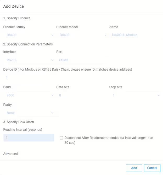
Device Serial Port Settings
Interface = RS232, COM5, Device ID = 1, Baud = 9600, Data Bits = 8, Stop Bits = 1, Parity = None, and Reading Interval = 1 Second.
Once the device has been added into the OEG Software then it will appear in the Devices screen at the top of the screen. It will also appear in the “3rd Party Device” screen as the D8400 is considered a third-party device within the OEG software.
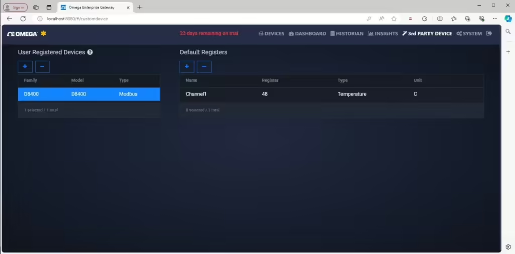
Channel Configuration
The Channel configuration screen is used to specify each measurement channel in a device. The channel configuration includes the Modbus register that contains analog data value, and the numerical data format. DGH devices store their analog data values in Modbus registers and the data values are represented as 16-bit unsigned integer values. Each register value represents the analog sensor data as a percentage of the full-scale input range. Use the Channel information screen to specify the channel Name, Value Type, Modbus Register, Measurement Type, and Measurement Units. See Figure 3.0 below.
The “Register Type” for each channel should be selected as “Measurement” and the channel should be “Enabled” for the program to read this channel value. The channel Name and Alias Name are strings of text or numerical characters that can identify the channel data. Example names may be “Boiler 1”, “Outdoor Ambient”, “Water Pressure” or any name that pertains to the application.
The “Register” numbers containing the analog data values are defined in the Modbus Register map located in the product User Manual. There are seven analog input Registers numbered from 40049-40055 in the D6000 and D8000 series modules. Analog input channel one is 40049. When specifying the channel value in the configuration screen, select the appropriate register, remove the “4” in 40000 to work with 49 through 55. Enter the register value minus one for each channel to be read. For example, channel one would be 49-1 or 48. Register number seven would be 55-1 or 54.
The “Value Type” for all channels should be selected as “Unsigned Integer 16-bit” as this is universal across all DGH Modbus measurement products. In this example, the channel type is selected for a K-Type thermocouple. Therefore, specify the “Measurement Type” as “Temperature” and the “Measurement Units” are “C” (for Degrees Celsius). At this point, the channel data values will be displayed as large unsigned integer values. Next, configure the channel “Data Value Scaling” to output the data in Degrees Celsius.
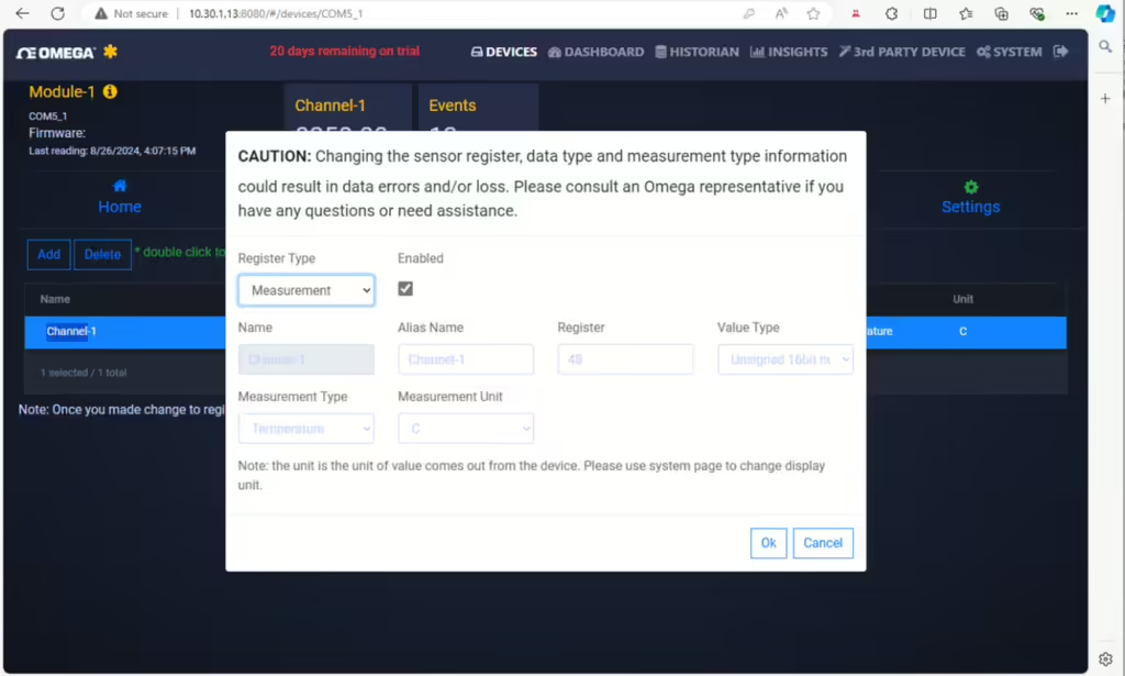
Data Value Scaling Overview
The Data Value Scaling feature is used to convert the unsigned integer data values from the module into usable engineering units such as Temperature. By entering both a Gain and an Offset value the OEG software can calculate, display and log sensor data values.
Each D6000 and D8000 series analog input module contains seven user-configurable input channels that support signal input ranges such as DC voltage, 4-20mA or Thermocouple inputs. The available signal types and ranges are model number specific. In most applications, the analog input range will be determined during system design and configured during the installation process. The signal inputs are easily configured using the DGH D6000 series Utility Software and the full-scale input range of each channel should be documented for future reference during the Data Value Scaling configuration below.
Begin the Data Value Scaling process by select the “Home” option on the left-hand side of the browser window. This should display the complete list devices configured in the software. Click on the Device that requires the scaling configuration. Next, highlight the channel to be scaled, and press the “Settings” option on the upper right side of the browser window. See the Figures 4.0, 5.0. and 6.0 below to arrive at the Scaling configuration screen.
The data scaling is performed using both a Gain and Offset value. The Gain value is calculated using the plus and minus full-scale measurement values for the selected channel type. In this example, Channel_1 is configured as a K-Type thermocouple input. The DGH product data sheet and user manual contain the plus and minus full-scale values for each measurement range. For a K-type thermocouple input range, the plus full-scale value is +1250 degrees C and the negative full-scale value is -150 degrees C. Use these values to calculate the GAIN value below.
Calculate the Channel_1 Gain value using the formula below and enter the value into the OEG software.
GAIN = (+FS – -FS)/65535
GAIN = (1250 – -150)/65535
GAIN = 0.02136263
Enter the value 0.02136263 into the Gain block. Then enter the range negative full-scale value (-150) into the Offset block on the screen. Press “Ok” to apply the changes. When the window closes the channel data should now be displayed in the degrees C units.
To locate the Device Value Scaling option, select “Home” in the web browser to list of installed devices. Then double-click on the device that requiring the data value scaling configuration.
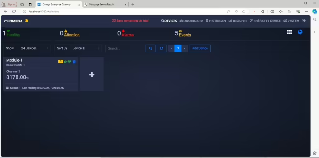
From the device channel list, select or highlight “Channel 1” and press the Settings selection on the upper right-hand side of the web browser window.

At the bottom of the device settings screen, click on the blue edit box indicated by the white arrow below and open the Value Scaling screen.

Temperature Input Value Scaling Example
Enter the previously calculated Gain and Offset values into the Value Scaling screen below. Check the “Enable” box to enable the scaling, select the Measurement Type as Temperature and select the Measurement Unit as “C” for degrees Celsius. The Gain and Offset values are explained again below Figure 7.0.
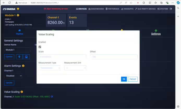
The Value Scaling formula used to calculate the Gain for a K-Type thermocouple input channel is:
Recall the analog input range +/- Full Scale (FS) values from above.
+FS : +1250 Deg C
-FS : -150 Deg C
Value Scaling formula
- Calculate the GAIN Value : Gain = (1250 – -150) / 65535 = 0.02136263
- Enter “0.02136263” into the GAIN box
- Enter -Full Scale value (-150) into the OFFSET box.
- Select the Measurement Type “Temperature”
- Select the Measurement Units “C” (in this case)
- Check the “Enable” box and press “Ok” to save the changes.
Voltage Input Value Scaling Example
Analog input channels configured to read DC voltages will utilize the Value Scaling Formula outlined below Figure 8.0. Perform the Gain calculation and then enter the Gain and Offset values into the Value Scaling screen. Check the “Enable” box to enable the scaling, select the Measurement Type as Voltage and the Measurement Unit as either “mv” or “V” for voltage or millivolt scaled readings.
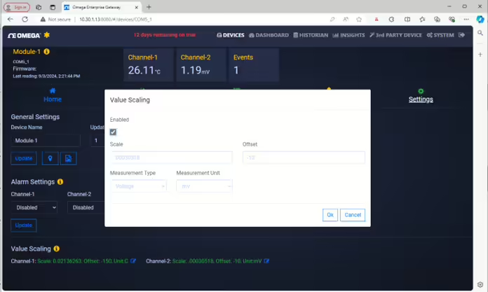
The Value Scaling formula will use the following +/- Full-Scale (FS) values for a +/-10V input channel:
+FS: +10
-FS: -10
Value Scaling Formula
- Calculate the GAIN Value : Gain = (10 – -10) / 65535 = 0.00030518
- Enter “0.00030518” into the GAIN box
- Enter -Full Scale value (-10) into the OFFSET box.
Measurement Units Selection
- “mV” = Voltage readings will be displayed as voltage, for example 1.54Vdc = 1.54.
- “V” = Voltage readings will be displayed as millivolts, for example 1.54Vdc = 1540.
- Check the “Enable” box and press “Ok” to save the changes.
Conclusion of Device Configuration and Data Scaling
This technical note has covered adding a DGH data acquisition module into the Omega OEG software, configuration of the serial communications settings, and illustrated the calculations required to properly scale sensor data values into engineering units. This process can be repeated for each additional module added into the software.
The data scaling Gain formula illustrated above will be the same for every channel. Importantly, know the input range +/-FS measurement values before performing the Gain calculation. The Offset term will always be the -FS measurement value. Using the formula and full-scale range values, the Gain and Offset values can be calculated and entered in just few minutes.
Combining DGH modules and the Omega OEG software, data acquisition systems can be configured quickly and easily at an economical price point. Using the OPC server functionality within OEG, sensor data values can be transferred to other programs and applications. This is very beneficial in process control systems. See the Omega OEG website for more information about the OPC server functionality.
About DGH Corporation
Established in 1985, DGH is an industry-leading manufacturer of data acquisition hardware for use in the process monitoring and control industry. Our products have been used worldwide in such industries as mining, water & wastewater management, pharmaceutical, scientific laboratories, military, transportation, energy sectors, and power utilities.
As part of Jewell Instruments, LLC, DGH Corporation continues to innovate products for use in a wide range of data acquisition applications. Our products have been designed into OEM applications such as emergency stop buttons and used by systems integrators across many industries. Contact a member of our sales team today and see if DGH can provide a solution for you.
Contact Info
DGH Corporation
(603) 622-0452
info@dghcorp.com