Analog Output Module Communicates with GE Fanuc CNC Machine GE FANUC Series 32i – Model B
Overview
Industrial CNC machines like the GE Fanuc Series 32i, Model B Series, often require analog output control signals for controlling external devices such as DC motors, annunciators and more. These analog signals are generated using devices installed inside a machine, or by using cost-effective external solutions connected to a serial port. The analog data values are often transmitted from the host CNC machine to external devices using industry standard protocols.
In some applications, the host CNC machine may not contain support for the standardized communications protocols. In this case, it will be necessary to use an on-board programming environment and a custom application program to write the analog data values to the external devices. This requires a program to process internal information, calculate analog output data values, ability to format the values into a command that the external device will understand, and then transmit the commands to the external device.
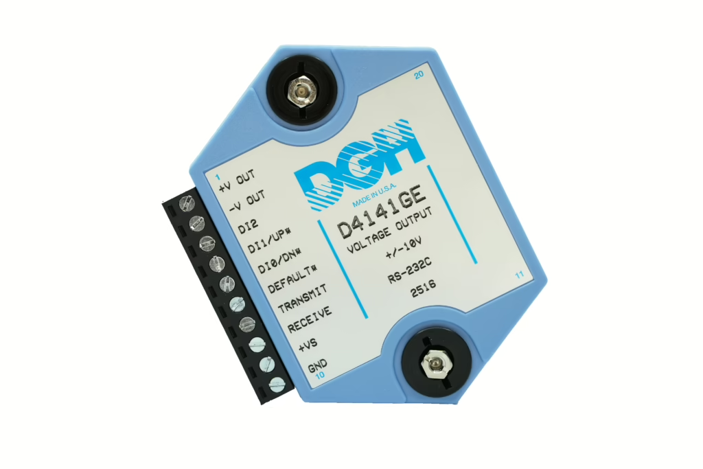
DGH manufactures a cost-effective and customized analog output module for communicating with the GE Fanuc Series 32i, Model B series CNC machines using the on-board programming language. The D4141GE module to communicate directly from the 32i Model B and generate +/-10Vdc voltages for controlling DC motors and more. With over 35 years of experience, DGH has a proven track record of manufacturing high quality analog and digital I/O products that communicate using widely recognized communications protocols. Making them an ideal solution provider for customers looking to generate analog DC voltages from a CNC machine like the 32i model B series CNC machines.
The D4141GE analog output module contains a high-resolution 12-bit analog-to-digital converter for generating the galvanically isolated +/- 10Vdc analog output voltage signal. The module communicates through an RS232 serial connection, other important features include user-programmable slew rates, a communications watchdog timer, programmable startup voltage signal, and an 8-bit analog to digital converter for verifying and reading back the analog output signal. The communications watchdog timer can be used to adjust the analog output voltage to a known “safe” condition in the event of a communications failure. See Appendix B below for additional hardware specifications.
Configuration
Before connecting the module to any machine, there are two important features to be configured for proper operation. The serial communication baud rate and the input data scaling values for generating analog voltages. These parameters are easily configured using the DGH Utility Software free download. Or they can be written to the module manually by typing the commands into a terminal program such as Putty.
The D4141GE input data scaling values are critical for generating the correct analog output voltage. To better understand how the input scaling works, we will use an example where a host machine will send values to a D4141GE module and output signal will be used to control the RPM of a motor. The motor requires a 0-10Vdc output control voltage which corresponds to 0-12000 RPM on the motor. To achieve this, the module input data range must be scaled to represent RPM values, same as received from the host machine.
The D4141GE module input data range is scaled using two commands, the input data MiNimum (MN) and MaXimum (MX) commands. The data values transmitted to the module with the MN & MX commands will equate to the analog output DC voltage minus and positive full-scale values respectively.
In this example, an input data value of +12000 (RPM) input must equate to +10Vdc voltage output. Use the MX command to configure the module for +12000 data input to equal +10Vdc output. Next, configure the minus full-scale data value. In the example, 0Vdc must equal 0 RPM. Since the module analog output is bipolar down to -10Vdc, the scaling must be calculated down to the -10Vdc signal output. Use the MN command to configure the module for -12000 data input to equal -10Vdc output.
The input data scaling process is now complete. All controller RPM values written to the module must now be within the numeric input data range of +/-12000.00, equating to a -10Vdc to +10Vdc voltage output. Values received that are outside this range will generate error messages from the module. See the table of Input Data Scaling Values, the Setup command and Input Data Scaling command examples below.
| Input Data Scaling Values | ||
| Input Data Value | Output Signal Value | |
| Minimum Values | -12000.00 | -10Vdc |
| Maximum Values | +12000.00 | +10Vdc |
Write Setup Command (SU) Values
To write the Setup (SU) values to the module, use the DGH Utility Software or manually write the values to the module using a Terminal program. Send the following command Setup (SU) command sequence to manually configure the module for a serial communications baud rate of 4800 baud, device address “1”, eight data bits and one stop bit. Other features can be controlled using the Setup command. However, those features are not necessary for this example application.
- $1WE
- $1SU310301C2
Write MN & MX Input Data Scaling Values
To write the scaling values to the module, use the DGH Utility Software or manually write the values to the module using a Terminal program. To manually write the scaling values to the D4141GE module then send the following minimum (MN) and maximum (MX) command sequences with their respective values to the module. After the values are written, the module can accept RPM data values as required in the example above.
- $1WE
- $1MN-12000.00
- $1WE
- $1MX+12000.00
All commands listed above must be terminated by a carriage-return character and the module will respond to each command with an “*” (Asterisk) character.
Generate Analog Output Voltage
Two commands are required to generate an analog output signal. The first command is used to transmit the RPM value to the module. The second command sends an Acknowledge (ACK) command causing the module to generate the requested analog output voltage.
The RPM values received from a GE Fanuc 32i must be properly formatted for the D4141GE to generate an analog voltage. The commands begin with a forward slash prompt character (/), a two-character command, polarity sign, and the RPM data value. An example command would be /AO+09500.00. In this example, the RPM data value must include the polarity sign, five digits of data, a decimal point, and two characters after the decimal point. This format cannot be altered, and all commands are terminated with a carriage return character.
A short time delay between the AO and the ACK command may be required for the D4141GE module to respond to the AO command and prepare for the ACK command. A delay of 100mS or higher should be adequate.
Manual Guide i Programming Example:
POPEN
DPRNT[/1AO+01000.00] // Output Value to D4141GE Module
DPRNT[/1ACK] // Acknowledge the Signal Change Request PCLOS

Appendix A – Configuration Information and Command Examples:
The following commands can be sent to the D4141GE module to configure the serial port baud rate and the input data scaling values. These commands can be transmitted using a Terminal program such as Putty.
Setup (SU) Command
Send the following command Setup (SU) command to manually configure the module for a serial communications baud rate of 4800 baud, device address “1”, eight data bits and one stop bit. Other features can be controlled using the Setup command. However, those features are not necessary for this application.
- $1WE
- $1SU310301C2
MN & MX Scaling Commands
To scale the D4141GE input data values, manually send the following minimum (MN) and maximum (MX) commands to the module. The module will then be configured to accept RPM values and generate analog output signals.
- $1WE
- $1MN-12000.00
- $1WE
- $1MX+12000.00
Note: All commands listed above must be terminated by a carriage-return character and the module will respond to each command with an “*” (Asterisk) character.
Appendix B – D4141GE Hardware Specifications:
Analog Output Signal
- Analog output range: ±10Vdc.
- Output isolation: 500V rms.
- 12-bit output resolution.
- Accuracy: 0.1% FSR max (Integral & Differential Non- linearity.
- Zero drift: ±30µV/°C
- Span tempco: ±50ppm/°C max.
- 1000 conversions per second.
- Settling time to 0.1% FS: 300µs typ (1ms max).
- Output change manual mode (-FS to +FS): 5s.
- Programmable output slope: 0.01V/s to 10,000V/s.
- Voltage Output drive: 5mA max
Analog Output Readback
- 8-bit analog to digital converter.
Power Requirements
- Unregulated +10V to +30Vdc, 0.75W max.
- Protected against power supply reversals.
Environmental Temperature Range
- Operating -25°C to +70°C. Storage -25°C to +85°C.
- Relative Humidity: 0 to 95% noncondensing.
Mechanical Dimensions
